Removing records from ISPadmin


Delete client

Deleted client is not deleted from the system, instead its record is excluded from active client list.

Delete service

Removed service is not deleted from the system, it is deactivated and hidden from list of active services. You have the following options in Client card.

icon lupa disShow deleted services Displays also already deleted services
 Restore cancelled service It enables to restore a deleted service using service edit.

Delete invoice

Standalone invoice You can icon delete invoiceCancel invoice from invoice detail in Client card / Invoicing, and then delete completely icon check ko from Invoicing Cancellations Invoices.
Bulk invoices

You will be allowed to delete issued invoices only if all of them are unpaid.

Delete router

A router can only be deleted if no service is assign to it. It will be deleted entirely, just its ID is stored in the database so it will be possible to add a new one with the same ID, and then re-define its settings.

Limited data consumed / Traffic graphs are high

If you experience one/both of the following problems

  • Limited data gets consumed within a short period of time (without a client actually using it) and/or
  • Traffic graphs of users go up to a speed which is not even set for the service,

then disable the Only router monitoring option in the router, which is used to manage clients and from which information about data transferred are retrieved. (Click here for more information)

Otherwise, traffic counters are not reset. If a counter reset does not take place on a particular MikroTik router, the system obtains data that seem to indicate that the amount of traffic passing through the router has been on the increase and assumes that the speed of a given client's connection has increased.

Add / Edit Router


HardwareRoutersAll, or Edit in the details box of a particular router.


General information

Router name A name of your choice. It will be displayed in the details box of a given router.
Locality

Define it in Settings Code lists Locations. Geographical group for routers. You can use it for cities or town districts, counties etc. It helps you with schematic displaying of routers. If you administrate more cities or villages, you can use the names of specific cities and villages. If you administrate only a few cities, you can use names of city districts. If your network is very extensive, it is more suitable to select distribution of locations into districts or regions. With this distribution you will significantly make more clear displaying of routers in individual system screens. It is also possible to filter records and client according to this division. For example: bulk email and SMS.

POP According to the configuration in Settings Code lists POPs
Group According to the configuration in Settings Code lists Router groups
GPS The coordinates of the location of a router. You can type them in or you can use the map at the bottom of the page to insert them (when you move the red pointer, the coordinates are updated automatically).
Address The address where a router is located. It can be entered In any format.
Description A description of a router + your notes This text is displayed when you hover over the name of a given router in the details box.
Internal ID An ID of your choosing. It is used for internal purposes. This ID can also be seen in Hardware Routers Router Status Routers in the Internal ID column.
  Superior device for Nagios
Router This item is used to define the logical topology for the Nagios system.
Device This item is used to define the logical topology for the Nagios system. For example, an external device connected to a monitored router. A switch can be connected to this device.
Report outages for Nagios If you check this box, device failures will be monitored for the purposes of Nagios. Also, you can select a group that will receive failure notifications - see Settings Code lists Nagios Contacts).
Router IP address The IP address of the interface through which a given router communicates with ISPadmin. When adding an IP address it is being checked against the database immediately. If already in use in the system a warning message will be displayed with router name which is used with the IP address. You will be able to save the form anyway.
Router type The type of the router used See supported types of routers.
QOS doing on router Here you can specify on which router QoS (shaping) will be done. It can be done either locally (on the very same router) or on a different router (on the router of your choosing).

Queue tree type

The system sets up its own queue tree in most cases. This one is a special client´s queue tree. It must be defined in Mikrotik manually and then loaded into the ISPadmin, and tested. QT can be selected only if 1:1 aggregation is used, otherwise the special QT is not displayed. Set up queue trees in Hardware RoutersAll.

Router is active The activation / deactivation of a router in the system (in the event of a failure or a replacement).
Only router monitoring If a router is in monitoring mode only, the system does not apply any configuration changes to it - it only passively gathers information.

Use API A new way of communication with MikroTik routers. We recommend that you activate this communication interface. ISPadmin is able to retrieve more data through API than through SSH.
Use DHCP If the system knows IP and MAC addresses, it can assign DHCP leases. The activation of the DHCP server and the assignment of addresses are automatically reflected in the configuration of a given MikroTik router (DHCP Relay). On every router update, before uploading the DHCP leases, the system removes dynamicly assigned DHCP leases.
Syslog monitor Here you can activate/deactivate the sending of syslogs from routers to the ISPadmin server.
Apply firewall rules If the box is checked, all clients entered into ISPadmin are added to the configuration of a given router. The whole range is dropped at the end. This ensures that no unauthorised access to this router is allowed. However, if you wish to add clients (step by step) to the router inISPadmin from your old system, you have to temporarily disable this option. Otherwise, the system would "cut off" your original clients.
Ping size Here you can specify the ping size.
SNMP community The password needed for retrieving SNMP data from a device. It can be set in Winbox in the IP->SNMP menu.

SNMP port/SNMP version Fill in only if you use a different port/version from the default one.
SSH user/password The username/password needed to log in to a router through SSH.
SSH port Default: port 22. If you use a different port, change this setting accordingly.
API port Default: port 8729. You can enter a different one.
Web interface port Again, if you use a different port from the default one, enter it here.
MAC filter

It is a firewall rule. An IP-MAC binding is established. Clients in whom this binding cannot be established are allowed to connect to their corresponding APs, but all their packets are dropped there.

More about the MAC filter in the FIREWALL section here.

Use wireless MAC filter The restriction of access to an AP by means of Wireless Access List. API must be functional for this feature to work. Clients whose MAC addresses are not listed among allowed addresses will not be able to connect to their corresponding APs. If this filter is active, clients´ MAC addresses will be stored in Mikrotik in /interface wireless access-list. MAC address of end device from client card is stored in wireless filter. If MAC address is not listed, and client´s MAC address is listed instead, this MAC address is stored in Mikrotik.
List of MAC addresses The system automatically loads MAC addresses from a router once an hour.
Activate radius Activate the RADIUS technology - a wide range of authentication options and comfortable provision of APs to mobile clients. You can use the Radius module only if you acquired a licence for it beforehand. Fill in the Password field.
Login of technicians to Mikrotiks via Radius You can make use of this feature if you want to restrict access to a certain router.

Router restart If a router freezes from time to time, you might want to schedule an automatic restart here (ideally to take place during the night) and its periodicity.


Firewall

Here you can add your own firewall rules for a given router. More about firewall rules in the FIREWALL section here.

<h3 class="textLabel">Routery</h3>
<ul>
    <li>Nyn&iacute; se při přid&aacute;v&aacute;n&iacute; nov&eacute;ho routeru ověřuje zad&aacute;van&aacute; IP adresa ihned po vyplněn&iacute; pol&iacute;čka ve formul&aacute;ři a neček&aacute; se až na ukl&aacute;d&aacute;n&iacute; fomul&aacute;ře. Je-li IP adresa již použita, zobraz&iacute; se ihned pod pol&iacute;čkem informace, kter&yacute; router m&aacute; tuto adresu použitou. Formul&aacute;ř je možn&eacute; uložit i s již použitou IP adresou.</li>
</ul>

Installation Modems

There are two different ways of adding cable TV clients to the system:

  • A new Internet service is created for a cable TV client. Afterwards, a boot configuration file (with the correct speed profile) is automatically generated. When you install the service in a given client’s place, you just connect a cable modem and it boots up. The network is then automatically configured via DHCP and the installation is complete.
  • The “installation” of cable TV clients may also be done in the following way: A particular modem is added to so-called installation modems. As a result, a boot file for this modem is generated. It then boots up anywhere in the network and the system recognizes that it is an installation modem based on its MAC address. The computer connected via this installation modem is able to connect to the network, but it can only access the administration interface of ISPadmin because it receives an IP address from the IP address pool reserved for installing modems and clients. After logging in to the administration interface of ISPadmin, a client is added to the system along with their IP address and personal details. The modem automatically reboots within five minutes. The client is assigned a new IP address. The connection is fully functional after this reboot.


When you are in the process of adding an installation modem, the most important thing for you to do is to enter the correct MAC (Media Access Control) address of this modem. It is a unique hardware address. Each device should have one assigned to it by its manufacturer. ISPadmin uses it to be able to recognize whether a particular modem is an installation one or not. The system then treats it accordingly (see the description of use of installation modems above).

You can also add a description of your choosing to each modem to be able to distinguish between them.


Install

Add a new client - see Add new contact.

Mikrotik guide


This document approximates crucial information necessary for proper understanding of cooperation between ISPadmin system and MikroTik routers. Without the following knowledge, you will not be able to correctly define important settings in ISPadmin.


Update of configuration of all routers is carried out periodically every 5 minutes. However, if you want to configure a particular router, you can update just its configuration, i.e. recording rules at any time by pressing Update the router configuration in router heading.


The configuration is transmitted differentially. This means that during configuration update the system firstly downloads the actual router configuration, compares it with the configuration that should be in the router and then transfers detected differences. This way the number of records on flash routerboard is minimized, leading to smaller number of defective blocks.
Router monitoring is done via SNMP, or API if activated. All configuration changes loaded by ISPadmin to a router are transmitted via SSH protocol, or via API. Active communication between router and ISPadmin is a prerequisite for its correct operation.


  • SNMP - It ensures router monitoring (traffic, transferred data, CPU, RAM etc.).
  • SSH - Loading of rules, automatic backups of configuration, both text and binary.
  • API - More advanced and faster communication with the router, reading of the ROS version, loading of rules, WIFI signal graphs (SIGNAL, NOISE, SNR, TCQ etc.).


To verify connection to router, press Test connection button in router heading. The verification is also possible for all routers by pressing the same button Hardware Routers All.


Add the routers in the monitoring mode first. It means that system is able to see the specified routers and displays them in administration, but it does not record any configuration changes on them. If a router is in "monitoring mode", the system just reads information by SNMP and possibly even API and shows different values​​, statistics and graphs in five-minute intervals.
So, if the router connection is working correctly, you can switch the router status from monitoring mode on to off which enables recording of configuration changes by SSH or API.


We consider versions 3.30, 4.17, 5.23, 5.6, and 6.x as stable.

Alternatively, you can use newer versions (6.x and higher), but we recommend you to deploy a new version on several minor routers first to test it, and if no problem appears, deploy it on the rest.

Despite all the precautions it may happen that you will damage functional configuration of a router. For this reason it is recommended to use the function of automatic router backups, thus you will shorten the time needed for rectification to a minimum. You can store router backups (MikroTik, Ubiquiti, Canopy, Flash linux) in text version. For MikroTik routers, you can also create binary backups {with backup command} which can be used for system restoration. Click on a respective icon to save the backup to local disk. You can simply load the backup into Mikrotik by "dragging" from local disk through the Winbox window into "Files” tab. To restore complete router configuration, select backup in Winbox and click on "restore” button.

ISPadmin completely records all necessary rules into Mikrotik routers configuration. In all cases, the system works just with those rules which have "ispadmin_" (Firewall, QueueTree, ppp) in comment, or "ispadmin_" (Mangle) in packet mark.

Thanks to this, it is possible to add your own rules of Firewall, restriction of Queue Tree etc. onto the router without them being touched later on. These rules remain in the beginning of Firewall, Mangle, Queue Tree, and ISPadmin does not modify them. The rules will be applied in given order, of course.

In case of manual change of any rule (e.g. via Winbox), which is recorded by ISPadmin, thus manually changed rule is overwritten by the original rule specified in the system during another configuration update. It is necessary to perform all settings changes such as rate of clients, tariffs, etc. from ISPadmin.

ISPadmin thus modifies just the following parts of configuration and it does not interfere with other parts of RouterOS:

/ip firewall filter

All firewall rules are recorded here. At first the IP addresses of clients, their end devices and routers, which are in the segment, are allowed, and at the end the entire subnet is forbidden in FORWARD by DROP rule. To make the addition of a new client into the system even possible, the entire subnet must be specified as "IP addresses for WIFI users" in Routers tab in Routed networks.

It is possible to switch off the firewall recording in the router settings by unchecking Apply firewall rules. If this item is not checked, the firewall rules will not be recorded into the router. You can use it e.g. if you still haven´t all your clients in the system. In this case firewall would block unspecified clients and so it is better not to apply firewall when entering existing clients into the system.

By default, the restrictions on IP addresses, SRC as well as DST, are recorded into firewall. In some cases (e.g. due to a reduction of number of rules in firewall) it is necessary to restrict only to SRC or DST. Define this type of firewall setting in Settings System Settings Mikrotik. The type of rules recording can be set in ID mikrotik_fw_drop.

Firewall structure which is recorded by ISPadmin :

FIREWALL and NAT rules were optimized into tree structure in ISPadmin 4.04. Similarly to MANGLE, FILTER and NAT will use tree structure for rule ordering according to the following:


  • FIREWALL rules
  • FILTER -| own rules(no ispadmin prefix)
  •               | ispadmin_first_forward
  •                          | ispadmin_first_(order)_(comment)
  •                                      .
  •                                      .
  •               | ispadmin_service_forward
  •                          | ispadmin_SSH_trust_server_(IP)
  •                          | ispadmin_SMTP_trust_server_(IP)
  •                          | rtr_(router name)_ispadmin_up
  •                          | rtr_(routeru name)_ispadmin_down
  •                          | dev_(device name)_ispadmin_up
  •                          | dev_(device name)_ispadmin_down
  •                          | switch_(switch name)_ispadmin_up
  •                          | switch_(switch name)_ispadmin_down
  •                          | ispadmin_services_mac_up
  •                          | ispadmin_services_mac_down
  •                                      .
  •                                      .
  •               | ispadmin_basic_forward
  •                          | ispadmin_group_src_(IP range)
  •                                      | iptel_(phone No.)_(id)_ispadmin_up
  •                                      | (client name)_ispadmin_(id)_up
  •                                      .
  •                                      .
  •                                      .
  •                                      .
  •                          | ispadmin_group_dst_(IP range)
  •                                      | iptel_(phone No.)_(id)_ispadmin_down
  •                                      | (client name)_ispadmin_(id)_down
  •                                      .
  •                                      .
  •                                      .
  •                                      .
  •               | ispadmin_last_forward
  •                          | ispadmin_last_(order)_(comment)
  •                                      .
  •                                      .
  •               | ispadmin_drop_forward
  •                          | ispadmin_drop_NETWORK
  •                          | ispadmin_DROP_SSH
  •                          | ispadmin_DROP_SMTP


This structure provides very detailed processing of firewall rules and an effective pass with increased performance (it is not necessary to process whole firewall tree e.g. with thousands of rules to find out rule at the end of the list) but the system search only in a few "jumps" in the tree structure where the rule can be found faster because the system searches the specific number of rules regarding the network mask. Define mask size (ranges divided by blocks) in Settings System Settings Mikrotik, ID mikrotik_mangle_net_block. Yet the option to write your own set of rules globally for all routers is maintained (Settings System Settings Mikrotik, ID mikrotik_default_fw) for tree beginning (ID mikrotik_default_fw_last) for set of rules placed at the end of firewall. This default set of rules may be appended by individual rules, which are specific for each router, and which are valid for the router only. You can add the rules while editing a router in firewall section. The rules concerned are First FW rule on the router and Last FW rule on the router. This ensures firewall variability.


Newly the system creates a list of IP addresses on the MikroTik router in address-list (name - ispadmin_DROP_NETWORS) , where all networks of clients' ranges are written in to drop traffic for non-registered clients. While updating routers, the system no longer deletes the list to add these new ranges but only disables the forbidding chain ispadmin_drop_forward.


/ip firewall nat


  • NAT rules
  • NAT ----| own rules(no ispadmin prefix)
  •              | ispadmin_first_(chain name)
  •                          | ispadmin_first_(order)_(comment)
  •                                      .
  •                                      .
  •              | ispadmin_first_dstnat
  •                          | ispadmin_remind
  •                                      | remind
  •                          | ispadmin_info_pages
  •                                      | info_pages
  •              | ispadmin_service_dstnat
  •                          | ispadmin_trustserver_https__(domain)
  •                                      .
  •                                      .
  •              | ispadmin_basic_forward
  •                          | ispadmin_disabled_user
  •              | ispadmin_last_(chain name)
  •                          | ispadmin_last_(order)_(comment)


Again, this structure provides very detailed processing of firewall in NAT section. Processing is similar to firewall filter rules. You can also select First NAT and Last NAT while editing router; functionality is similar to firewall filter rules.


Each client with suspended service is recorded in NAT which ensures re-directing of his traffic to Info page which you can edit in Settings Info Page. Client suspension is done in Client card for Internet service. Here you can also select Reason Suspended which impacts which info page will be displayed.


ID mikrotik_nat_disable_users must be set to 1 for the rules to be written to NAT. To do so, go to Settings System Settings Mikrotik. 0 means no rules are written to NAT. This can be used for cases when forwarding of suspended clients is resolved outside ISPadmin. If ID mikrotik_nat_disable_users = 2, records of suspended clients are written into address-list and only 3 rules for each suspension reason are created in NAT, rather than writing 3 rules for each suspended client. Allowed servers as defined in Settings Info Page Allowed Pages are part of these rules. These servers may be used by clients, e.g. for paying unsettled invoices.


In ISPadmin, writing rules to NAT pools relates to firewall nat section. This functionality ensures writing of rules of netmap type. These enable you to do DSTNAT 1:1. For writing DSTNAT address to be active on router you have to set mikrotik_nat_for_end_user to 1 in Settings System Settings Mikrotik. If ID is set to 0 DSTNAT is not writen to Mikrotik. If you enable automatic writing the following rule is added for each DSTNAT and SRCNAT client:


/ip firewall nat add action=netmap chain=ispadmin_first_dstnat comment=ispadmin_NAT_1.2.3.4_10.10.0.100 dst-address=1.2.3.4 to-addresses=10.10.0.100

/ip firewall nat add action=netmap chain=ispadmin_last_srcnat comment=ispadmin_NAT_10.10.0.100_1.2.3.4 to-addresses=1.2.3.4 src-address=10.10.0.100


Another set of rules ensures safe forwarding of clients to Overdue page. Turn this functionality on in Settings Info pages Overdue, ID remind_pay = 1. Some other parameters with an impact on this functionality may be added: Number of days for repeating of notification, Number of days after due date, Display notification while reaching the total amount owed. This set of rules is written to ispadmin_remind section in Mikrotik.


The last set of rules is written into ispadmin_info_pages; it forwards clients to Info page as defined in Settings Info pages Inf. zprávy. You can only create one active rule for including a client on a list. 


/ ip firewall mangle


900px Mangle winbox


Here the mangle rules of packets are applied, which means that a client gets a "packet mark" in the shape of "ispadmin_ID", where ID is a unique client number in database. If the client has more of IP addresses or if he has other "IP ranges" specified in Internet service settings, then all these IP ranges have the same packet mark and this way they are restricted in the same Queue Tree.


Since the 3.65 beta1 version, the work with MANGLE rules is completely redesigned, thanks to which the router power - dealing with larger quantities of packets - should increase.

All MANGLE rules are divided into groups, so that each packet does not have to go through all the rules that are saved in MANGLE in the router, but in case that the packet bumps into a group (CHAIN), for which it is designed, then it just goes through a limited group of MANGLE rules.


The basic groups are created automatically as follows:


  • -- CHAIN ispadmin_first_pre - PREROUTING - currently rules for an automatic reminders regarding nonpayers are added here (Remind). For now no other rules are added here.
  • -- CHAIN ispadmin_first_post - POSTROUTING - this target is empty for now and it is possible to use it for your own needs. If you need to apply some rules in POSTROUTING, it is possible to create your own ones and add them into ispadmin_first_post chain. The system will neither affect, nor overwrite these rules of yours in any way.
  • -- CHAIN ispadmin_first_forward - FORWARD - this CHAIN serves for now for the authorization of service MAC addresses, which are defined in Settings Administrators Admin MAC. A respective address list is created to contain allowed MAC addresses. For more information see Changelog 3.60 beta1.
  • -- CHAIN ispadmin_group_pre / ispadmin_group_post - these two chains are designed for mangling of packets for incoming and outgoing traffic for individual client services.


The chains are automatically divided into smaller groups of blocks of IP addresses with mask /26. This way the browsing through rules on a router, where a large number of clients is, will speed up considerably, because every packet goes through the previous rules until it gets to the ispadmin_group_pre rule. This rule is automatically divided (according to IP address) into e.g. CHAIN ispadmin_group_pre_192.168.7.0 (number of subgroups always depends on the range of IP addresses, which are set for the router). Consequently every packet which goes through a router and has the source IP address from the range 192.168.7.0/26, just goes through a subgroup of several rules from this range (mangle in router for other ranges does not interest this packet at all) and does not have to browse for instance thousands of rules (on a "larger" router). This should lead to a considerable speed up of processing the MANGLE queue. Subgroups are divided by mask /26 on the first level. You may change this division in Settings System settings Mikrotik, ID mikrotik_mangle_net_block. You can set up the mask in the range of /24 - /30 here. It is necessary to consider this division according to the number of used networks on a router.


In Settings System Settings Mikrotik, there is ID mikrotik_default_mangle_first. Here you can add your own set of MANGLE rules, which will be included at the beginning of all MANGLE rules and will be applied first. The rules look like this: /ip firewall mangle add ......... Each rule is on a separate line. These rules are applied on all Mikrotik routers.


In Settings System Settings Mikrotik, there is ID mikrotik_default_mangle_last. Here you can add your own set of MANGLE rules, which will be included at the end of all MANGLE rules and will be applied last in case that they have not been used in any of the previous rules (pass-through function is not applied). The syntax is similar to mikrotik_default_mangle_first. These rules are applied on all Mikrotik routers.


You can define your own set of MANGLE rules for each router; they will be applied first, or last. Fields Opening mangle (applied as first) and Ending mangle (applied as last) are ready for you while editing a router.
You can use your own comments inside the rules. Each comment must begin with #. A rule with comment may look like this: /ip firewall mangle add ........ # My comment or as a new line beginning with # My comment. During processing, all comments are removed prior to writing to router; they just help you with orientation in the rules.


The rules are processed as follows:


--- defaul MANGLE rules applied to all routers (mikrotik_default_mangle_first)
--- special MANGLE rules applied to a specific router
--- CHAIN "ispadmin_first_pre"
--- CHAIN "ispadmin_first_post"
--- CHAIN "ispadmin_first_forward"
--- CHAIN "ispadmin_group_pre"
-- split of MANGLE rules according to source IP address and grouping
--- CHAIN "ispadmin_group_post"
-- split of MANGLE rules according to target IP address and grouping
--- default MANGLE rules applied to all routers
--- special MANGLE rules applied to a specific router

You can define default firewall rules which are written to all routers with SSH access in Settings System settings Mikrotik, ID mikrotik_default_fw. This way you can e.g. restrict sharing of OS Windows, spreading of specific viruses by blocking particular ports.
Rules which are stated in default firewall always have to begin with /ip firewall filter add. Rules that are not defined this way will be ignored.


Example of default firewall:


/ip firewall filter add chain=forward protocol=tcp dst-port=135-139 action=drop comment="netbios"
/ip firewall filter add chain=forward protocol=udp dst-port=135-139 action=drop comment="netbios"
/ip firewall filter add chain=forward protocol=tcp dst-port=445 action=drop comment="netbios"
/ip firewall filter add chain=forward protocol=udp dst-port=445 action=drop comment="netbios"
/ip firewall filter add chain=forward src-address=10.0.0.0/8 protocol=udp dst-port=53 action=accept comment="DNS"
/ip firewall filter add chain=forward src-address=10.0.0.0/8 protocol=icmp action=reject reject-with=icmp-admin-prohibited

You can activate MAC filter for each Mikrotik router (Ubiquiti is optional). Check MAC filter item in Mikrotik for activation. If the MAC filter is active, then IP and even MAC address of a client will be recorded into firewall (firewall filter section). If client changes IP or MAC address, the Internet will not work.
The system automatically loads MAC addresses from a router once an hour. If you have activated MAC filter and you connect a new client, you do not need to fill in client´s MAC address. In this case, ISPadmin enables the client in firewall and when the client is connected, it will read his MAC address from ARP table, and stores it. IP address is then linked to MAC address and locked.


If it is necessary, in some cases, to switch off the automatic loading of MAC addresses at a particular client, then fill in "-" (dash) instead of a MAC address. This way the client IP address will be authorized on firewall and the lock of MAC will not be carried out. This is used in cases of e.g. two computers being used on one IP address (laptop, PDA, etc.).


You can switch off automatic reading of MAC addresses for all clients globally in Settings System Settings General, ID macfilter_getusermac.

ISPadmin will write rules into Queue Tree based on tariff setup. Simple Queue is not supported because it does not enable the settings of those parameters as Queue Tree does. The system “multiplies” defined tariff speed prior to writing to Queue Tree by rate_exponent value. You can define the value in Settings System Settings General. Rate_exponent value determines the actual speed a client will get. Default value is 1.2, so 1024 kbit/s is written to Queue tree as 1228 kbit/s. This increase of tariff speed basically "covers" client´s protocol overhead and potential packet loss, which may occur on WiFi. The client will be satisfied because of higher speed than is actually agreed in the contract. Sometimes it is impossible to explain to the client that if his speed is 1024 kbit/s, then due to the reason of protocol overhead the download speed of 128 kB/s will never show up in his browser.
You can define all parameters, such as speed, line type, burst, aggregation etc. in Settings Tariffs.

!! global-in, global-out are obsolete from OS 6.x version; a unified global value is used!!!


For each router, you can select Queue type from pop-up menu. This settings impacts the way Queue tree is processed. The options are global-in and global-out. These are important for correct router operation. You have to study packet path according to RouterOS 6.x scheme thoroughly.


700px Packetflowv6


See scheme relevant for RouterOS 3.x/4.x


If the QOS (Quality of Service) is performed on a central router, this option is inactive, because MANGLE is governed by the settings of the central router. If a change of router settings is performed (e.g. from global-in to global-out), then at first Queue Tree and MANGLE are completely deleted and consequently set again according to the new settings. (Only for OS versions < 6.x) Global parameter is used for new OS versions. This is done for reasons of “cleaning” of all Mikrotik tables so that rules are not written incorrectly.


Possibilities:


global-out


Default router settings.
Packets in direction from client (dst-address) are marked in POSTROUTING in MANGLE.
Packets in direction to client (src-address) are marked in PREROUTING in MANGLE.
This settings is used in case that NAT is used on router, because the packets are correctly marked and the correct addresses of clients are shown in POSTROUTING, not just their NAT-ed changed public addresses.
The disadvantage is that every packet must go through entire firewall causing higher router load. In case that even NAT is performed on a router, this is the only option how to apply QOS and a data stream restriction on a client.


global-in


Packets in direction to client (src-address) and also from client (dst-address) are marked in PREROUTING in MANGLE.
Using global-in reduces router load.
This option, however, cannot be used in case that even NAT is performed on a router. In this case client download would not be limited, because the packets enter the Firewall still changed by NAT (under a public address), and so they are not correctly marked and thus not included into a correct Queue Tree.

QoS


You can select QOS doing on router from router pop-up menu for router on which shaping is done. If you select Local QoS is done directly on this router. If you selected a different router from the menu, the client shaping is performed on a target router. If the shaping is set on a different router (not locally), then a note, stating that clients on this router are shaped on a different one, will display in the router header. During adding or editing Internet service, in the case of clients shaping on a different router a note will display when selecting a router, where it is specified on which router the shaping is carried out.


Local shaping has an advantage that client is restricted already at the nearest access point and the overall shaper load is reduced, because at each access point only a few clients are restricted. The disadvantage is, however, that if you use aggregated tariffs, e.g. if you have 3 clients with an aggregated tariff 1:10 at an access point, then for this number of clients the resulting aggregation is 1:3. In this case it is better to use central shaping, which shapes clients on one router e.g. from five APs (e.g. within a city). This way there will be more clients on one router and the aggregation will apply. The disadvantage of central shaping is that you need more powerful hardware, which is able to shape larger numbers of clients.

For each Mikrotik router, you can select Apply firewall rules from pop-up menu. If you select Local firewall is done directly on this router. If you selected a different router from the menu, the client firewall is performed on a target (superior) router. If the firewall is set on a different router (not locally), then a note, stating that clients´ firewall on this router is done on a different one, will display in the router header.

On a Mikrotik router it is possible to set "ratecontrol” system, which is important for a correct function and proper ensuring of the connection quality. Set it up in Queues / Queue type.

!! ISPadmin does not perform this set up itself, it is up to each administrator to do so. ISPadmin uses “default” type while writing queue tree rules. So if you prefer “sfq” type set it up for default class. !!


900px Queue type


Types of Queues:


PFIFO - Packet First In First Out
PFIFO and BFIFO send packets as they arrive. This means that the packet that arrives first also leaves first. This settings of "QueueType" is not suitable for shaping, because it is not possible to ensure a meaningful shaping. It causes line “congestions”, high response times etc. This type of QT is set by default and it is necessary to change it!


SFQ - Stochastic Fair Queueing
It is a simple algorithm that ensure equal network use by all active data streams. However, it does not ensures fair use among users or programs, but e.g. among individual TCP connections. It creates more queues, into which it distributes individual TCP connections and UDP streams according to the hash function. These queues are processed by the"round robin" algorithm. Every connection has a chance to be processed and one bulk data stream does not overload the majority of the line capacity. The hash function is changed in time and this way the collisions are solved (two streams do not stay in the same queue for a long time).


RED - Random Early Detection
It is designed for busy backbone connections. According to the calculated statistics, it reduces the load by dropping packets. The closer the total traffic is to the maximum value, the more the packets are dropped. This algorithm does not provide any options of shaping and treats all data streams equally. However, it does not have such a high computing demands on busy machines and maintains the maximum throughput and the lowest line delay.


PCQ - Per Connection Queue
It facilitates the restriction of greater number of unshared lines. It is similar to SFQ with some additional functions. It enables using identifiers of individual data streams (dst-address | dst-port | src-address | src-port) and it is able to set up speed limits for individual data streams via pcq-rate.


Link: http://wiki.mikrotik.com/wiki/Manual:Queue

A simple QT is set, with separated upload and download. In case of this tariff (for instance 1024/512) a client can download 1024 kbit/s and upload 512 kbit/s (altogether 1,5 Mbit/s) at the same time.


900px Qt fd 

Both upload and download are also restricted for this tariff. These QT are inserted under a superior QT at the same time, which ensures that the client can download individually 1024 kb/s and upload 512 kb/s, but if both run at the same time, then the total sum of these rates will not exceed 1024 kb/s. The advantage is that client during testing of rates runs a test, which tests separately download and upload, so everything is OK. However, if client is downloading and also using e.g. torrent which uploads at the same time, client speed in both directions is not exceeding 1024kb/s.

Ispadmin_7837_down download is “0” for this line type settings. This is correct because speed is limited to superior "queue ispadmin__7837". This way you save router CPU because QT is limited only once in the superior QT. Speed of superior QT is actually identical with download speed, so it is not necessary to restrict it individually. If the line had speed of 1024/1024, then “0” speed would be set even for QT ispadmin_7837_down. QT´s are technically not necessary, but they can be written for reasons of data counting, graphs creating, and statistics even with zero speed.


900px Qt hd

When using this aggregated line a superior line is set, and calculated according to the formula:


(download * number of clients) / aggregation = total aggregated line


Practical example - in case of an aggregated line 1:10 with speed of 1024/512 and with 20 clients, the total line is calculated as follows:


(1024 * 20) / 10 = 2Mbit/s


A 2 Mbit/s line is thus established on a Mikrotik (if rate_exponent is defined download/upload values are multiplied by the exponent), and all clients with this aggregation are assigned to it. The entire „aggregation“ group is set dynamically according to the actual number of clients. So, if there are 40 clients in the aggregation group, the entire aggregation group will have 4Mbit/s. Every client, who is assigned to this aggregation group, is restricted to max. 1024/512, so none of the clients will have more than 1024/512 (if burst is set it will be applied), with the fact that upload and download are summed (as well as with the classical HD tariff) and as well all these clients together will not exceed 2Mbit (again in upload and download altogether).


900px Agr hd


In our example a QT of shared HD tariff is displayed. It is 1024/512 kb/s tariff with 1:2 aggregation. According to the formula specified above, the "superior" line "shared_629" is calculated. Three clients, who are limited to 1024/512, are classified into this line and this download + upload is is even further generally restricted for each client to 1024 kbit, which limits the sum of download + upload (for instance Test_user1__7837).

If the aggregated line is of FD type, then the separation of download from upload is performed in the aggregation group. This means that speed calculation is performed for each direction separately. So, in case of the aggregated FD line 1024/512 with the aggregation 1:10 and number 20 of clients, the following speed calculation is performed for download:


download = (1024 * 20) / 10 = 2Mbit/s upload = (512 * 20) / 10 = 1Mbit/s


So, an aggregation group is thus established separately for download (2Mbit) and for upload (1Mbit). Into these two groups, the download and upload of all clients within this aggregation group is assigned.


900px Agr fd


Here the shared HD tariff 1024/512 kb/s with the aggregation 1:2 is displayed. In this case, the download rate (shared_629_down) is calculated separately and for upload (shared_629_up) as well. Upload and download of all clients with this tariff are assigned to these two aggregation lines separately.

In some cases it is necessary to assign clients into a special QT, e.g. to divide traffic on a router into three groups, where each group represents one connection, for instance into another village. Each connection has its own defined capacity (e.g. 2Mbit).

In this case it is necessary to create a special QT on Mikrotik for each group and define appropriate speed, or set other parameters of this QT manually, because every provider has different requirements, or it is necessary to create more deeply nested structures of the QT, which it is not possible to create automatically.

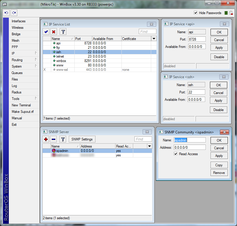
It is necessary to create named QT (which will be entered into the system) on Mikrotik. If the QT is called e.g. VIP, it is necessary to create the following on MK:

VIP – clients with HD tariff will be assigned to this QT (upload and download are shared)

VIP_IN – download of clients with FD tariff is assigned to this QT

VIP_OUT – upload of clients with FD tariff is assigned to this QT


900px Qt spec


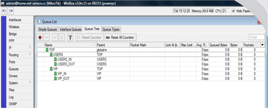
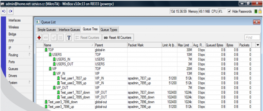
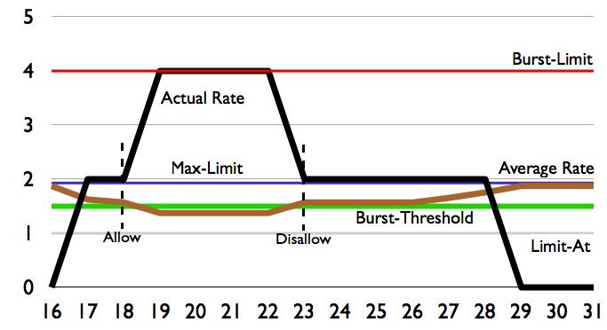
There are 2 client groups - USERS and VIP - created on the example figure above. Speed parameters are defined for each group accordingly; total group speed and download/upload speed are set, it is also possible to allocate here additional restrictions, such as the restriction of P2P nets, or connection totals...

You can adjust the entire tree according to your needs. The system is "interested" only in the "end branches" of the whole tree, where the clients will be assigned. In our VIP example, it is VIP, VIP_IN and VIP_OUT. It does not matter at which level the end "branch" of the tree is located.

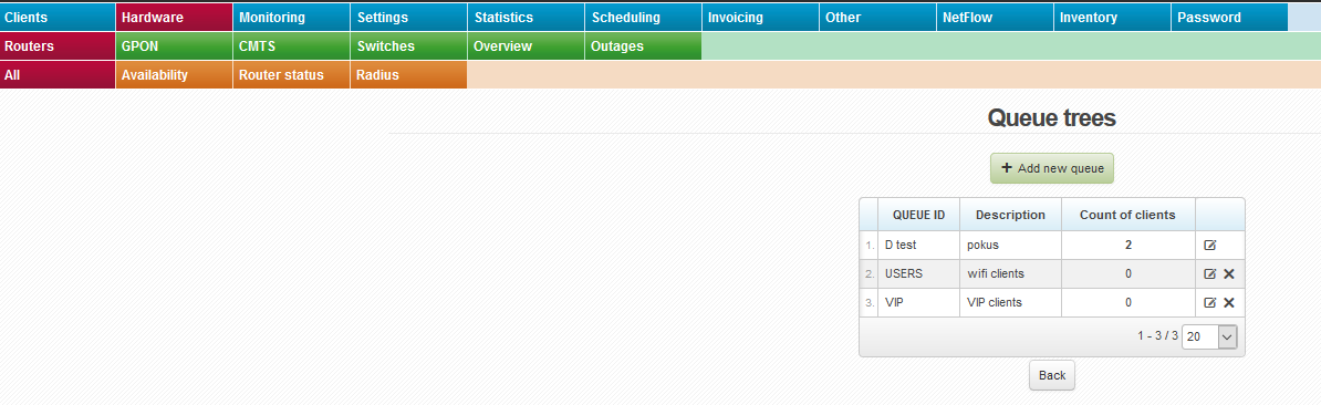
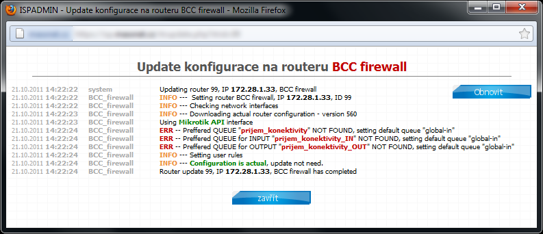
Now you have let ISPadmin know that there is the special QT VIP. To do so, enter it to Queue tree in router heading (Routery). Enter special QT “VIP” here. You do not have to enter QT VIP_IN and VIP_OUT. The existence of these QT is assumed while entering QT VIP. If QT VIP_IN and VIP_OUT are not present in MK (syntax is important; you have to use the same name as in ISPadmin and Mikrotik, plus add suffix _IN and _OUT in capital letters), so the clients with FD tariff will be assigned to QT “global-out” (only “global” for ROS > 6.x) outside this “tree”.


Queue Trees 

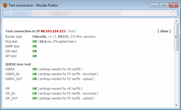
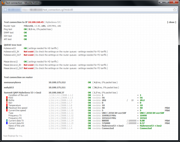
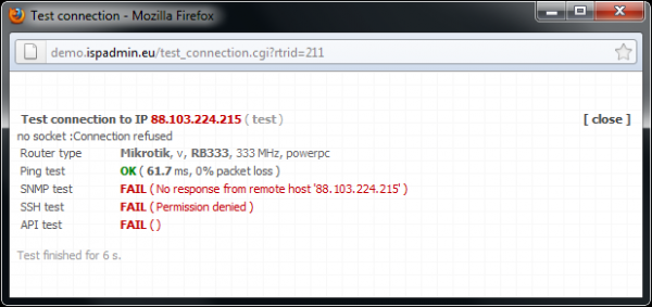
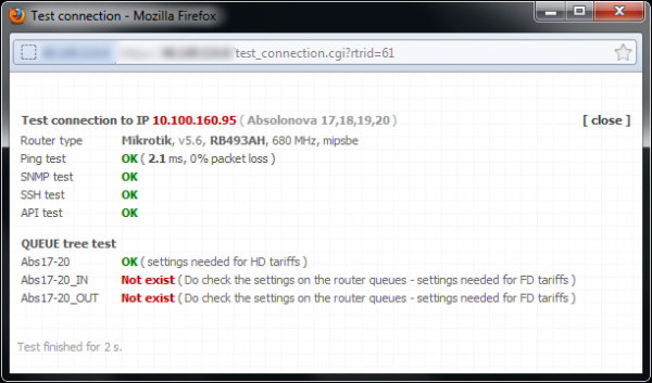
Click on Test connection to test special Queue tree; the test should run flawlessly.


Connection test


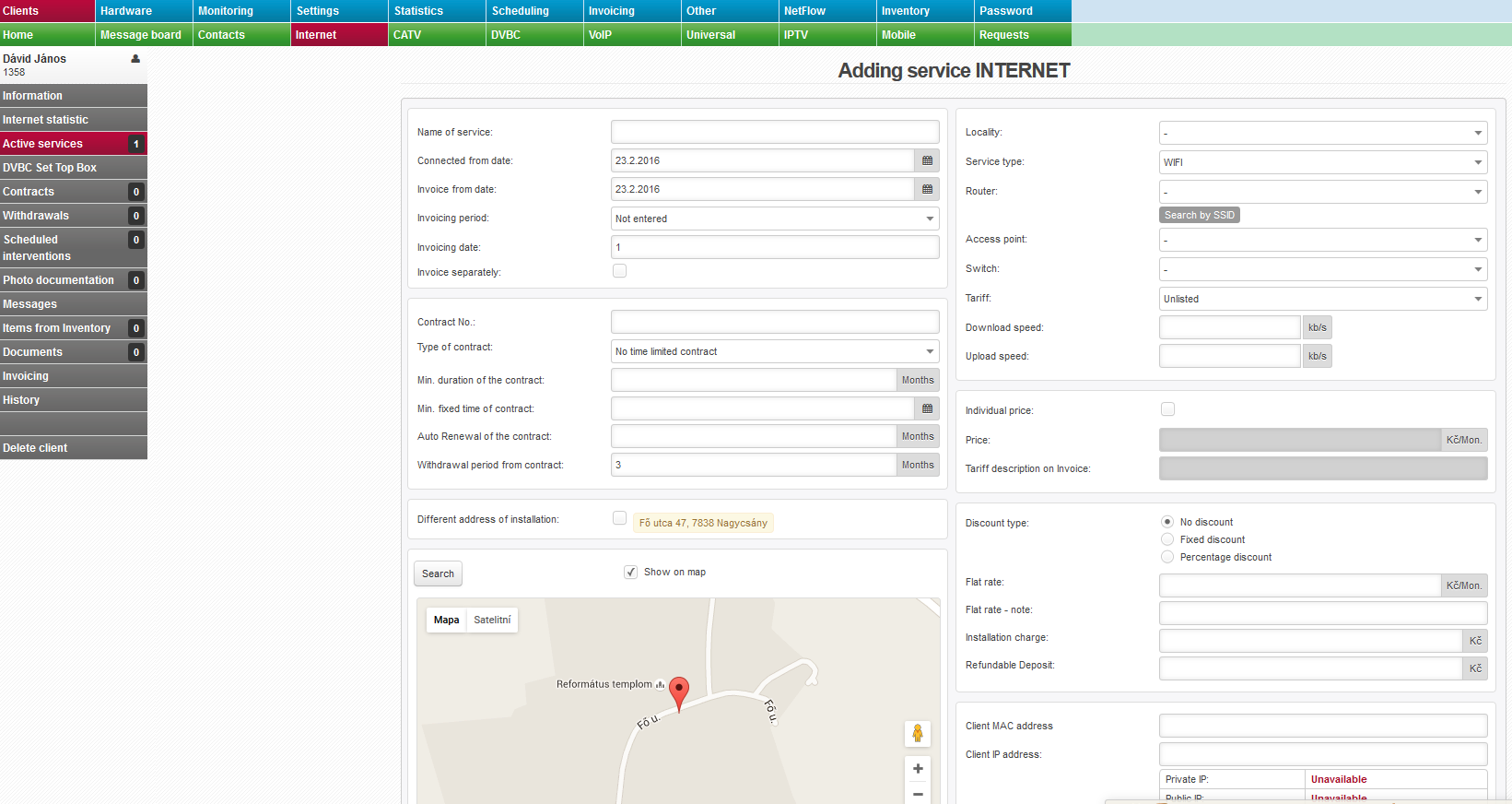
If QT are defined correctly on router and the test runs OK, you can assign client to this special QT. You can do so while adding/editing Internet service in Client card. Select a tariff, a pop-up QT menu appears (if the aggregation is 1:1) where you select QT to which a client is assigned. QT can be selected only if 1:1 aggregation is used. Otherwise QT selection is not displayed. The reason is that if client is assigned to aggregated (shared) tariff you cannot assign him to a special QT since client cannot belong to both, aggregated line and special QT at the same time. Technically, it is not possible to mangle client package twice. A packet can have only one packet mark and so it can logically belong only into one line (aggregated or shared).


Sluzba INT


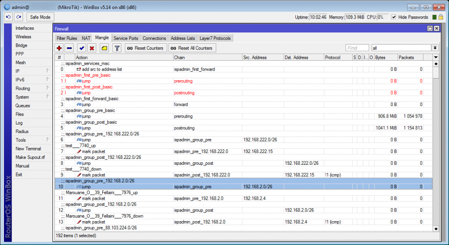
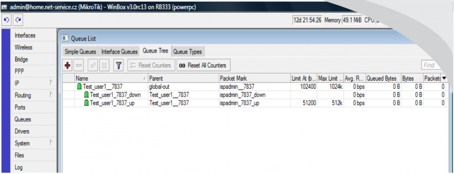
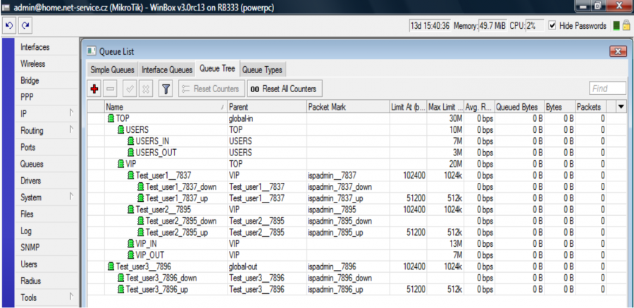
So if you assign client Test_user1 to QT VIP it will be classified in Mikrotik as follows:


900px QT VIP


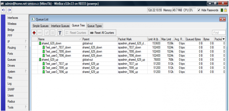
All clients have tariff 1024/512 with aggregation 1:1 and it is a HD tariff. Clients Test_user1 and Test_user2 are assigned to QT VIP. Client test_user3 is normally assigned to "global-out", because he has no QT set. Since it is a FD tariff, clients´ download and upload will be divided into VIP_IN and VIP_OUT .

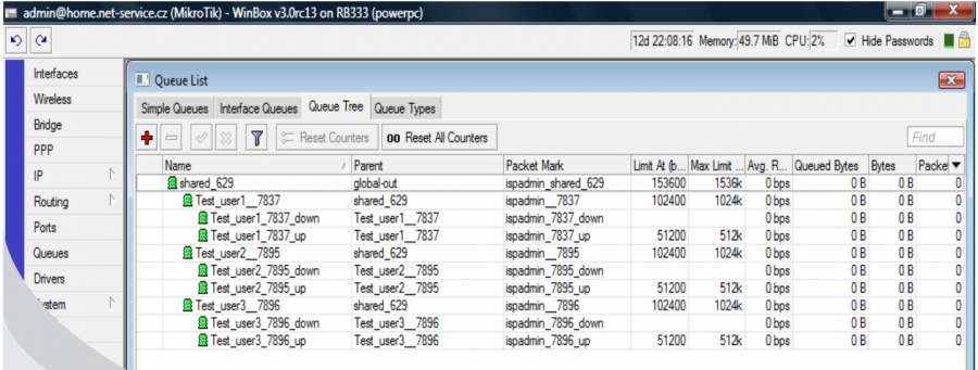
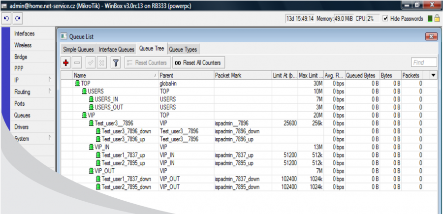
If it is HD tariff, then the clients will be classified as follows:


900px QT VIP HD


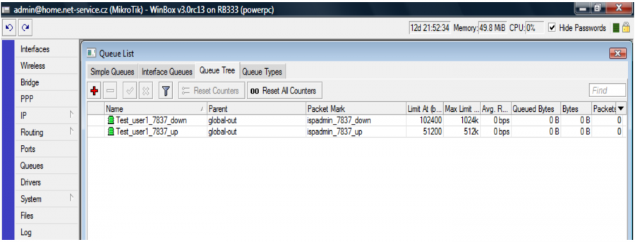
Clients Test_user1 and Test_user2 are assigned to QT VIP and not in VIP_IN and VIP_OUT as for HD tariff. All clients have a usual HD tariff where download/upload are limited on superior QT, e.g. Test_user1__7837. Client Test_user3 is assigned to "global-out".

You can combine the above-mentioned procedures as needed. In our example, clients Test_user1 and Test_user2 have FD tariff with 1:1 aggregation and speed 1024/512. Client Test_user3 has HD tariff 256/256, therefore he is assigned to QT VIP.


900px QT VIP FD


mikrotik_preffered_queue - All clients must be assigned to a certain QT in some cases. E.g. in case we need to precisely set the overall speed of the line. You can set it according to the previous method, by assigning each client into a particular QT. However, this method is quite tedious and prone to mistakes by not adding a client into a QT and so he will automatically be assigned to global-out. This is why you can define QT to which clients are automatically assigned in case they are not explicitly assigned in another QT (Settings System settings Mikrotik, ID mikrotik_preffered_queue.) Again, if you set mikrotik_preffered_queue "VIP", then there must be created QT VIP, VIP_IN, and VIP_OUT on a router. The default value of ID mikrotik_preffered_queue is global-out.

Configuration update is carried out every 5 minutes. If no change occurs on router, such as client tariff change, router configuration change etc. router configuration remains unchanged. In case that the configuration update is performed, then only transmission of changes is carried out and the entire delete and the consequent re-uploading of the configuration is not performed. The system will download current rules from Mikrotik configuration and compare them with its own configuration, which should be in the router, and consequently will transfer the changes on the router. This way the number of records to the router flash memory will be minimized.

If you need to run configuration update (outside regular interval) do so from command line by running:


/usr/local/script/ispadmin/update_conf.pl


If you run the command for configuration update without a parameter, then a hint will appear with the list of routers, including their ID:

Auto mode according to system status, i.e. only routers with some system modification - service add, service parameters change etc. - are updated:


/usr/local/script/ispadmin/update_conf.pl auto


It generates new DOCSIS files for all modems:


/usr/local/script/ispadmin/update_conf.pl gendocsis


It generates new DOCSIS files for router with give ID:


/usr/local/script/ispadmin/update_conf.pl gendocsis


Upload of configuration to all routers:


/usr/local/script/ispadmin/update_conf.pl reload all


Upload of configuration with given ID:


/usr/local/script/ispadmin/update_conf.pl reload


Hard upload (master reset) of configuration with given ID:


/usr/local/script/ispadmin/update_conf.pl reload force


New generation of configuration on all routers - use with care, it creates a big system load (deletes all rules managed by ISPadmin from all Mikrotik parts and re-loads them):


/usr/local/script/ispadmin/update_conf.pl master_reset all


New generation of a specific router configuration:


/usr/local/script/ispadmin/update_conf.pl master_reset


Available routers:


ID IP Mode DHCP mode Router name
91 88.103.224.215 online stopped home
101 10.0.0.1 online stopped mk1


If you need to update router No. 91 (internal unique router number displayed in router heading), run


/usr/local/script/ispadmin/update_conf.pl reload 91 force


The result looks like as follows:


16.2. 2009 13:24:30 system Updating router 91, IP 88.146.172.90, home
16.2. 2009 13:24:30 home --- Setting router home, IP 88.146.172.90, ID 91
16.2. 2009 13:24:30 home --- Checking new network interfaces
16.2. 2009 13:24:30 home --- Downloading data from router
16.2. 2009 13:24:32 home --- Setting client restrictions
16.2. 2009 13:24:32 home --- Updating router configuration 1/2 ( 3360 b - rows 10 )
16.2. 2009 13:24:32 home --- Updating router configuration 2/2 ( 360 b - rows 2 )
16.2. 2009 13:24:32 home --- Checking QTREE dependency
16.2. 2009 13:24:33 home --- Updating router 91, IP 88.146.172.90, home completed
 

If you need extended debug information, set ID mikrotik_qt_debug to 1 in Settings System Settings Mikrotik.


Router connection test

Hardware Routers All

Click on router updateUpdate all routers (test connection to all routers), or test a given router by clicking on router update Update the router configuration.


Basic test is Ping availability. If there are active services SNMP, version v1, SSH, or API, they will be tested, too. If there are independent Queue Trees on a router, their settings will be verified, too.

A preview of Test connection screen along with SNMP data from connected device. SNMP data is in raw output version.

600px Test1

This is an unsuccessful connection test. You may need to configure or check configuration of login credentials.

600px Test2

Verification of individual Queue trees if defined on router.

600px Test3


ISPadmin automatically writes difference configuration to routers every 5 minutes.

icon info2 Manual update of MikroTik router configuration can also be run from the command line: /usr/local/script/ispadmin/update_conf.pl. Usage: if you need to run the update at once, following changes in configuration.

The most convenient way to run manual configuration update is by clicking on router update. By clicking on the icon, you will open a new progress window.

To display a complete list of commands that are sent to MikroTik via API or SSH, set ID qt_debug=1 in Settings System Settings Mikrotik. This way you can pinpoint discrepancies if you experience problems with writing commands to a MikroTik router. When using API, you will see information whether a command has been successfully executed, or not. You cannot use this for SSH, for it does not return errors.

Router must be active for the router update icon to be displayed. Also, the router must not run in monitoring mode which only serves for reading information, not for its writing. You have to allow SSH, or API in Mikrotik IP / Services for correct functionality.

Update konfigurace qt_debug=1

Router monitoring

If router is monitored, the system does not copy any configurations, it barely passively reads information via SNMP, or API. If   Only router monitoring is not checked (Hardware Routers All, router edit), which is a common status, configurations are copied (mangle, shape, firewall, dhcp...) to routers via SSH service and API interface.

icon info2 Heading of routers in passive mode is grey whereas blue heading means active router - rules are recorded. White header means inactive router.  Hardware Routers All

So if you add all routers from your network into the system you will get a complete overview of all routers in one place. There are better monitoring options in Nagios integrated monitoring system which sends outage notifications.


alert icon Never leave router in such a mode so as to ISPadmin cannot connect to router via wrong access data (i.e. API, SSH, or SNMP protocols flash in red). This mode may cause unexpected server load leading to system failure. We recommend you to switch router to INACTIVE mode!!!

Switch router to operation mode

If you are sure that routers and the Internet services are set up correctly you may proceed with the last step - connecting clients to your network - which means to copy settings made in ISPadmin into router configuration. Switch off   Only router monitoring

All changes stored on routers will be applied within 5 minutes following their modification. You can also run the process of router configuration update manually via router update Update the router configuration which has an immediate effect.

Binary backups of MikroTik routers not working


The most common error messages regarding binary backups are:


  • Mikrotik ERR: Failed to save system configuration backup
    Mikrotik ERR command: /system backup save name="ispadmin"
    If binary backups don’t get saved, first check if the account used by ISPadmin for router configuration has FULL rights. If not, binary backups cannot be used.
  • scp timed out while trying to connect to ip_address
    This error implies that ISPadmin cannot log into the router via SSH. Verify SSH access manually. If you are able to connect to router via SSH manually, yet binary backups do not work, the problem might be in connection via SCP. Reinstall OpenSSH client to fix problem with binary backups. To do so, run

    apt-get remove openssh-client; apt-get install openssh-client openssh-server ssh


You will find more information on router backups in Other Backups Routers.


Download burst


BurstThis function enables you to temporarily (often only for a few seconds) increase client’s download/upload speed. The advantage of this is that the web pages and small files, such as photos and so on, load rather quickly but downloading larger files or P2P communication do not exceed the download speed which the client pays for. This positive impression will be made at speed measuring, too. When a client verifies their download speed rate on various web pages, a higher download speed than the one in the contract shows to them if the Burst values are correctly set. Most clients are then satisfied with the surfing speed but the downloaders are still within the limits of the given tariff.


Burst limit


Maximum download speed in kbit/s for the time of an increased speed. It is suitable to set double download speed of given tariff for the result to be visible. Assigning of this speed is only a few seconds according to the Burst time settings.


Burst threshold


Limit in kbit/s at which the Burst function is activated. The value must be lower than the download speed of given tariff. After the Burst time has elapsed, the download speed gets back to the tariff value during the whole time of downloading. Next Burst activation will be carried out only at the moment when the download speed decreases under the given limit.


Burst time


The time in seconds for which the increased speed will be set. Optimum value is 10 secs. You can enter 20secs for better results of speed measurement.

You will find official information on Burst functionality on Mikrotik routers at http://wiki.mikrotik.com/wiki/Manual:Queues_-_Burst.

ISPadmin configuration in Settings Tariffs.

icon info2 All settings analogically apply for upload, too.


Service activation on MikroTik routers


Winbox aktivace sluzebAn active communication between router and ISPadmin is a prerequisite for its correct operation.

  • SNMP - Router monitoring, (cpu, mem, trafic, uptime, etc.).
IP / SNMP - [SNMP settings] > enable, [+] New SNMP community > name, read access
  • SSH - Communication with router, configuration is read.
IP / Services - activate SSH service
  • API - Complete communication with router, status communication, Wifi signal reading, Mikrotik status, etc.
IP / Services - activate API service (TCP/8728)


User rights to access MikroTik router


900px Winbox nastaveni opravneniAlso, to ensure correct communication between a router and ISPadmin you have to assign FULL Mikrotik rights to user that will be used by ISPadmin for connection to router. Sole right for write is not sufficient for creation of binary backups.

Can the system monitor latency and packet loss rate for each device?


Yes, all devices (including client devices, if you want) are monitored and graphs are plotted of latency and packet loss rate.


How to set up a UBNT router


1. Define the IP address range for clients on the router where shaping is done (if shaping is not done centrally).
2. Do not set up this router as an access point. Set up the UBNT router to which a client is connected as an access point.
3. Select the shaper in the QoS doing on router item in the UBNT router settings.
4. Then you can check the MAC filter box (only monitoring --> active) and the Use wireless MAC filter box.
5. Choose an appropriate access point in the Internet service settings.
6. The MAC filter is applied to the UBNT router and the client in question is assigned to this router.


Under what conditions does the WiFi Clients at AP section appear in the overview of routers?


  • Set up a particular device as an access point and specify where shaping is to be done (QOS doing on router).
  • Assign clients to this access point in the Internet service settings.
  • Set the show_hw_end_equipment key in Settings Syst. settings General to 1.

Rules were modified in the default firewall. Later, a reset was performed. Now the rules do not work (the way they are supposed to).


1) Make modifications to the default rules again.
2) Log in to the console through SSH as the root user.
3) Run the script /usr/local/script/ispadmin/update_conf.pl master_reset all. This will perform a master reset on all active routers.

Retrieving routing table from MikroTik routers


If there are more than 1,000 rows in the routing table on a Mikrotik router, the table won´t be retrieved via API since it is very likely it contains all dynamic routes which means a long time for its processing leading to the failure of the script for time out.

The reason for this is that ISPadmin must be able to work with less capable routers, too. Retrieving the routes is not critical for the functionality, whereas router update is performed.

Creating ACCESS LIST

In a situation where the router Mikrotik is only an AP without any routed network and clients, and also has QOS set on his parent router. It starts to write the clients, that are assigned to this access point, to the Access-List(included AP-TX-LIMIT, CLIENT-TX-LIMIT according to the settings for internet services).The Routers have to be listed as active and their API, MAC filter, wi-fi Mac has to be enabled.

How to mass delete clients' MAC addresses

You can see the following icon - MAC FILTER - in the header of a router with the activated MAC filter. Click on it and choose one of the choices offered. Finish the process by clicking on the Delete all MAC a. button.


Tips on how to use this documentation


Search

Searching required information is possible either via structured menu which is divided into sections, or via full-text search of the entire contents of this on-line documentation.
Breadcrumbs

This aid will make it possible for you to find out where exactly you are at the moment.

If, for example, the following appears beneath the main menu - ISPadmin Wiki / ENG / Client management / Menu - CLIENTS / Clients / Message Board / Groups - it means that you are:


  • in the Wiki documentation of the ISPadmin system
  • in its English localization
  • in the Client management section
  • in the Clients tab
  • in the Message board subtab
  • in the Groups sub-subtab

Changelog

It contains newly added functionalities and modifications of the system which are displayed by versions and issue date. Changelog articles are also displayed in individual sections / pages of the documentation which relate to new functionality or modification. 

Basic orientation

You will find a welcoming menu with basic instruction on trying / implementing / using below. 

FAQ

Frequently asked questions along with most important procedures and settings are listed in FAQ section. 

Colours

Items which refer to real system menu are highlighted in corresponding colour, including their graphical background. Eg. Invoicing Settings Templates Reminders. This is also a working reference to an article. 

CONTACT

NET service solution, s.r.o.
Žerotínova 3056/81a
787 01 Šumperk
Czech Republic