
Switches
Here you can see all the switches that have been entered into the system as well as the status of communication with these switches via SNMP.
![]() For automatic retrieval of clients on switch ports to work, it is first necessary to activate the macfilter_getusermac_switch option in Settings Syst. settings General. The basic prerequisite for the automatic retrieval of clients is that the switch in question operates at layer 3 of the OSI model.
For automatic retrieval of clients on switch ports to work, it is first necessary to activate the macfilter_getusermac_switch option in Settings Syst. settings General. The basic prerequisite for the automatic retrieval of clients is that the switch in question operates at layer 3 of the OSI model.
+ Add switch
| Title | The name or description of a switch |
| IP | The IP address of a switch |
| MAC | The MAC address of a switch |
| GPS | Enter the exact coordinates of the location of a given switch, or make use of Google maps on the right - use the red cursor to pinpoint the location and the coordinates will be entered automatically. If you want this switch to be displayed in Other Map, leave the Show on map box checked. |
| SNMP community | SNMP community is the password for SNMPv1 and SNMPv2. It has to be the same as the one set on a given switch. Otherwise, the switch will not be available via SNMP and information about ports will not be retrieved. |
| SNMP port | Communication with a switch uses port 161. If there is a firewall between ISPadmin and a switch, it is necessary to allow communication via this port. Communication uses the UDP protocol. |
| Router | Choose one of the routers from Hardware Routers All, or leave the field blank. |
| Locality |
You can choose a location for every switch that does not have a superordinate router. You can assign such a switch to a particular POP. Define it in Settings Code lists Locations. Geographical group for routers. You can use it for cities or town districts, counties etc. It helps you with schematic displaying of routers. If you administrate more cities or villages, you can use the names of specific cities and villages. If you administrate only a few cities, you can use names of city districts. If your network is very extensive, it is more suitable to select distribution of locations into districts or regions. With this distribution you will significantly make more clear displaying of routers in individual system screens. It is also possible to filter records and client according to this division. For example: bulk email and SMS. |
| POP | POPs can be set up in Settings Code lists POPs. |
| Switch type |
Choose one of the following options: Backbone - This type of switch does not allow you to change port status or assign clients. Furthermore, clients are not assigned automatically to individual ports. You can recognize a backbone switch by its background color in the overview - light green. |
| Exact Type | Default setting: General switch. The general switch is automatically added to the Switch group in Hardware Settings End devices. It uses the Default switch SNMP template - Settings Other SNMP OID - which is also added automatically. |
| Switch Template | See Settings Switches |
| Active Link | If a device has its own administration interface, you can set up a link to it (HTTP or Telnet). |
| Ping Size | You can adjust the size of the ping packet for a given device. |
| Note | A text of your choosing to be added to the switch in question |
| Superior device for Nagios | |
| Router | This item is used to define the logical topology for the Nagios system. |
| Device | This item is used to define the logical topology for the Nagios system. For example, an external device connected to a monitored router. A switch can be connected to this device. |
| Report outages for Nagios | If you check this box, device failures will be monitored for the purposes of Nagios. Also, you can select a group that will receive failure notifications - see Settings Code lists Nagios Contacts). |
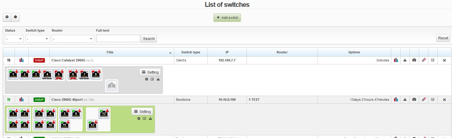
List of switches
In the list of switches, there are the following details and options:
| The status of Nagios notifications | |
| The graph of the availability of a device The system periodically ping a given device. The graph is plotted based on the results of these checks. | |
| SNMP SNMP | If the SNMP status is displayed in red, it means that the system is not able to communicate with a given switch via SNMP. As a result, it is necessary to check whether the switch and the SNMP community are configured correctly. |
| Title | When you click on the name of a switch, an overview of ports will appear. (If you want to see an overview of ports on all switches, click on ) |
| IP | You can ping a switch by clicking on its IP address. |
| Router | The name of a superordinate router. If you click on its name, details about it will appear. |
| Uptime | The time period for which a given router has been running without interruption. |
| When you click on the icon, detailed traffic graphs for individual switch ports will appear. | |
| Alerts for a given switch. More on alerts here. | |
| Photogallery | |
| You can test the connection between a given switch and the corresponding router by clicking on this icon. A superimposed window will appear with details of the communication between the switch and the router. | |
| Edit / Delete a switch |
Ports
|
If you hover over a port icon, information about a given port and the amounts of data transferred will be displayed. |
|
|
Display ports in the form of a table - text mode
|
|
| You can switch to edit mode by clicking on this icon. If you do that, all ports retrieved via SNMP are displayed (including terminal console, VLAN and other special ports). You can mark any of them and choose the desired action from the Setting pop-up menu. | |
| Select |
LAN ports: select all LAN ports on a switch |
| Change status | Turn ports On/Off: All communication is forbidden on ports that have been turned off (these ports are marked with a red cross in the graphical overview). |
| Uplink | Turn Uplink On/Off: If a port is set up as Uplink, it is not possible to connect a client to it. |
| Port pairing | Set up/Cancel pairing: In some cases, there is a “double” port on a switch. Such a port is a combination of, for example, an Ethernet port and a GBIC port. However, it is possible to use only one of them at a time. Some switches return via SNMP a separate OID for each of the ports and it is not possible to distinguish which port is currently being used. Therefore, it is necessary to set it manually. You have to choose two ports and do the pairing by clicking on the Set up pairing option. A single port is displayed twice in the system, but both the ports have the same number and all the information displayed is the same (because, in reality, only one port is used at any time). You can pair an extra port with any other port. In the process, a pop-up window will appear in which you will be able to choose which port is the Master port. It is the number of the port to which a cable is physically connected. The Slave port is then marked as unretrieved and has the same number as the Master port. |
| Way of data retrieving | Automatically: The port is displayed on the basis of the defined rules. Always show: The port is always displayed. Never show: The port is displayed only in edit mode. |
| Other settings |
Add note: You can add your own notes to individual ports. Such a note is then displayed in the info box that appears when you hover over a particular port. You can also add a note to a port when assigning a client to a certain port in the Client card. Remove clients from ports: remove clients from ports |
Assigning a client to a port
You can assign new clients to particular ports in the Client card when you are in the process of adding / editing an Internet service. You choose a specific switch and port. Additionally, you may add a note.